Signal Requirements for Time Tagger Inputs
Learn what signal types, voltage ranges, and pulse shapes your Time Tagger can detect, including trigger levels and minimum amplitude requirements.
Maximum Input Voltage Amplitude
For each model, we specify an input signal range:
- Time Tagger 20: 0 to 3 V
- Time Tagger Ultra: -3 to 3 V
- Time Tagger X: -1.5 to 1.5 V
Amplitudes slightly beyond the limits can still be applied without causing damage, but specified performances are not guaranteed. Please have a look at our brochure.
If your signal has an amplitude outside the accepted range, we recommend using SMA attenuators.
Note: The Time Tagger 20 can accept only positive signals. To work with negative polarity signals, it is recommended to adapt the signal using a pulse inverter. See the corresponding section: Recommended Pulse Inverters for Compatibility with Time Tagger 20.
Minimum Pulse Amplitude and Duration Requirements
For all Time Tagger models, we specify a minimum input signal amplitude of 100 mV. The minimum pulse duration requirements are as follows:
- Time Tagger X: 350 ps
- Time Tagger Ultra: 500 ps
- Time Tagger 20: 1 ns
While these values provide a useful baseline, it is important to consider a few additional factors, as reducing specifications to single numbers does not tell the full story:
- When the trigger level is properly selected and the system is correctly set up, these specifications guarantee a 100% count rate and a time jitter below the specified value for each model.
- Shorter or smaller pulses can still be detected, but this may result in:
- A count rate below 100% (missed events).
- Time jitter exceeding the specified values.
- These specifications for amplitude and duration are interdependent:
- Shorter pulses might still work if their amplitude is higher than 100 mV, while meeting jitter specifications and avoiding missed events.
- Conversely, longer pulses with an amplitude slightly below 100 mV may also function correctly.
By carefully tuning your setup, you can optimize the performance of your Time Tagger, even when operating near the specified limits. Please have a look at our brochure.
Suitable Pulse Shapes for Time Tagger Measurements
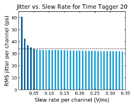
The Time Tagger detects electrical signals that rise or fall across a user-defined trigger level. Such events are acquired with a resolution of 1 ps and a specific time jitter for each model. This is independent of the input signal’s shape (square, triangle, sine, or any arbitrary shape), as long as the signal’s slew rate is sufficiently high to be detected by the Time Tagger within the specified timing accuracy.
Our Time Taggers detect rising/falling edges within the specified accuracy for slew rates of 0.05 V/ns or higher. Please refer to the figure below for a quantitative understanding of the timing jitter of our Time Tagger 20 for different slew rates.
For sine waves, 3-volt amplitude signals at approximately 3 MHz, or 1-volt amplitude signals at approximately 10 MHz, have slew rates of about 0.06 V/ns, which are accurately acquired by our Time Taggers.
Please note that Time Taggers working in HighRes mode provide the specified RMS jitter when the slew rate of the incoming pulses is higher than 0.2 V/ns.

Setting the Appropriate Trigger Level
Choosing the appropriate trigger level depends on the characteristics of your signal. Our general recommendation is to set the trigger level to half of the signal’s maximum amplitude, as this typically corresponds to the steepest part of the signal.
Additionally, whenever possible, select the sharpest edge of the signal, either the rising edge (positive channel number) or the falling edge (negative channel number). A steep signal edge results in better time definition and is less sensitive to noise compared to slower transitions, which are affected by noise for a longer duration.
To further optimize reliable detection, especially in cases involving noisy signals or pulses with parameters near the detection limit of the Time Tagger, we provide trigger level scan scripts in the Python and MATLAB examples included in the installation folder. These scripts can help fine-tune the trigger level for your specific use case. By default, the scripts can be found following the paths below:
- Python example:
C:\Program Files\Swabian Instruments\Time Tagger\examples\python\1-Quickstart\2-controlling-the-hardware - Matlab example:
C:\Program Files\Swabian Instruments\Time Tagger\examples\Matlab\1-Quickstart\2-controlling-the-hardware