Intensity Interferometry

Introduction to Intensity Interferometry
Intensity Interferometry is a sophisticated technique used in astrophysics to measure properties of distant stars, such as their angular diameter, structure, or emission mechanisms. Originally developed for radio frequencies and consequently adapted to optical frequencies, the intensity interferometry achieves high precision by correlating intensity fluctuations of light independently captured by two or more telescopes 1, 2.
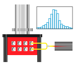
In intensity interferometry, the signal results from detecting coincident photons arriving at two remote locations within a short time interval. By calculating the correlation of these intensity fluctuations, either through analog signals or photon-counting methods, researchers can infer important properties such as the angular diameter of a star 3. Due to the weak nature of the signals, intensity interferometry often requires long measurement times and careful noise management 4.
Unlike Michelson interferometry, which requires the physical combination of optical paths to measure the phase and amplitude of collected light waves, intensity interferometry independently detects intensity fluctuations at separated telescopes and determines angular measurements through correlation analyses. Because it directly analyzes intensity signals, without the need for precisely controlled optical paths or beam-combining optics, the optical setup is simpler and easier to align. Furthermore, intensity interferometry offers enhanced precision and robustness against atmospheric phase disturbances, making it ideal for high-resolution imaging in photon-limited astronomical observations 5.
Timing Electronics and Their Role in Intensity Interferometry
Timing electronics in intensity interferometry provide the nanosecond-to-picosecond “stop-watch” that converts individual photon detections into the statistical correlations used to recover stellar structure.
A typical setup collects starlight with a telescope, couples it into single-mode fibres, spectrally narrows it with Fabry–Pérot or interference filters to lengthen the coherence time, detects photons with Single-Photon Avalanche Diodes (SPADs) or fast Photomultiplier Tubes (PMTs), and feeds the electrical pulses to high-resolution time-taggers for real-time computation.
During acquisition, the electronics enable picosecond-level time-stamping of every photon. For short-baseline laboratory experiments, a single time-tagging unit beside the detectors is sufficient, streaming timestamps directly to a host PC. When the detectors sit on telescopes separated by several tens of meters at least, synchronisation becomes a bottleneck for independent acquisition systems: a common timing and frequency reference (GPS, PTP, or White-Rabbit) phase-locks multiple units and compensates residual path-length delays on the picosecond level.
Common challenges in Intensity Interferometry:
- Insufficient timing precision: The thermal-light bunching peak that carries the astrophysical information is only a few tens of picoseconds wide. In addition to the intrinsic jitter of the timing electronics, the jitter from the detectors, cabling, and reference clock can blur the peak and lower the measured visibility. Keeping the total added timing uncertainty in the picosecond regime is therefore mandatory for competitive signal-to-noise ratios.
- Scalable multi-channel acquisition and wavelength multiplexing: State-of-the-art experiments deploy tens of single-photon detectors to increase the collecting area or cover multiple spectral bands. Splitting starlight into independent wavelength channels further enhances sensitivity by creating parallel correlation measurements across the spectrum. For this reason, timing electronics require multichannel capabilities that are synchronized to ensure a real-time measurement of the data.
- High-throughput data: Large multi-detector experiments generate enormous timestamp datasets that can overwhelm storage and add complexity to the analysis. By performing real-time correlation calculations, raw data doesn’t need to be stored on disk, significantly reducing data volume and simplifying processing.
- Real-time delay management: Telescope motion, temperature-dependent fiber delay, or nightly reconfigurations can shift the optical path difference during an observation. In conventional approaches, one would aim to physically adjust the cable lengths as a compensation mechanism, though this approach is not scalable. Timing electronics with adjustable delays or hardware filters onboard can help maintain the correlation peaked at on the fly.
- Crosstalk: Electric crosstalk between closely spaced channels of time-to-digital converters adds false coincidences that can masquerade as a correlation signal. Simply offsetting channels with different-length cables might not be sufficient, because thermal expansion of the cables can change their length, which changes the hardware delay and re-introduces false peaks.
- Long-baseline synchronisation: When detectors are coupled to telescopes separated by tens to thousands of meters, independent time-to-digital converters must share a frequency and timing signals to stay phase-locked.
Swabian Instruments’ Time Taggers as a Solution for Intensity Interferometry
Swabian Instruments’ Time Taggers address the limitations of intensity interferometry measurements with the highest precision, channel scalability, and real-time processing capabilities. Additional features to highlight:
High Timing Resolution for Maximum Visibility: Swabian Instruments Time Taggers achieve timing jitter down to 1.5 ps, giving intensity interferometry setups the stopwatch accuracy they need. This picosecond precision keeps the thermal light bunching peak sharp, so visibility remains high during long integrations and over wide baselines.
Multi Channel Capabilities for Synchronous Measurements: All the input channels are fully equivalent and independent, removing constraints around channel assignments. This provides users complete control over experiments, and the ability to activate additional input channels over-the-air, without requiring new hardware to facilitate scaling up the setups. It is possible to acquire from up to 20 input channels in a single system, and to seamlessly synchronize up to 8 systems for a total of 160 input channels operating as a single effective Time Tagger.
Versatile Acquisition and Fast Data Transfer Rates: Flexible, real-time filtering options can be implemented on timestamped data, including conditional filters and event dividers. These allow for reducing data volume on the hardware level before transfer to the analysis PC, optimizing throughput without losing key information. The Time Taggers can transfer data via USB 3.0 for up to 90 MTags/s. For higher rates, an FPGA link option is available in the Time Tagger X to achieve up to 1.2 GTags/s via qSFP+.
Delay Adjustments: From an acquisition perspective, Swabian Instruments’ Time Taggers can timestamp both rising and falling edges to better evaluate the pulse profiles. In addition, implementing channel-specific hardware signal delays and adjustable dead times facilitates the compensation for varying cable lengths and signal afterpulsing. Channel-specific signal delays can be applied on the fly, enabling precise alignment of incoming signals for robust and adaptive correlation measurements.
Remote Synchronization of Time Taggers for Very Long Baselines: For setups where telescopes, detectors, and other components aren’t co-located, Swabian Instruments provides a Software Workflow (see Tutorial) that aligns multiple remote Time Taggers to a common timebase, given externally disciplined frequency (e.g., 10 MHz) and 1 PPS signals. By enabling ReferenceClock at each site, the devices adopt that external reference, and a client-side TimeTaggerNetwork merges their streams on-the-fly so correlation and coincidence analyses run exactly as if every detector were plugged into one single unit, equally reliable for bench-top separations and km-long baselines.
Crosstalk Elimination for True Correlation Visibility: Analog crosstalk is eliminated by timestamping each signal with a separate Time Tagger driven by the Swabian Instruments Synchronizer hardware, which distributes a common clock and sync signals over SMA to every unit. In software, the synchronized taggers behave as a single object, streamlining correlation and coincidence analyses. By aligning timestamps across units, this setup suppresses false coincidences that often obscure the real signal in intensity interferometry. The result is clean, artifact-free correlation data that reveals astrophysical signals without induced electronic crosstalk.
Versatile Integration with Popular Programming Environments: Swabian Instruments supports multiple programming environments, including Python, MATLAB, LabVIEW, C++, and more. Our libraries and APIs empower users to build custom workflows and automate complex experiments, whether through code or via the intuitive TimeTaggerLab GUI, in which one can use virtual channels since our latest release. Using virtual channels, users can also process the data simultaneously during the capturing process, which allows the implementation of data calculations and algorithms on-the-fly for almost real-time processing.
Application notes
Time-Correlated Single-Photon Counting (TCSPC) with Single Quantum EOS SNSPD System
TCSPC_Swabian_Instruments.pdfCustomer success stories
Brandon Ginkemeyer, Harvard
I really like the Swabian Instrument’s usability and reliability. A senior student in my neighboring group said that the Time Tagger is his favorite instrument.
Read moreDr. Ted S. Santana, NPL
My experience with the Swabian Time Tagger has been excellent. It is a truly plug-and-play device with intuitive and user-friendly software.
Read more


Related News
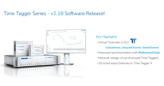
Time Tagger Series - v2.18 Software Release!
Swabian Instruments is excited to share the new Time Tagger Software v 2.18. This update brings powerful new tools, better performance, and easier ways to collect and understand your data. It’s designed to help scientists working in fields like quantum optics, life sciences, and time-resolved measurements.
Read more
The First Photonic Quantum Computer in Germany: Swabian Instruments' Role in this Breakthrough
Quantum technologies are transforming our world. The study of quantum particles brings us closer to realizing technology that once seemed impossible. From revolutionizing quantum research and advancing drug development to cryptography, there are fields where quantum computers are positioned to surpass even the best classical supercomputers. This month is marked by great news—the launch of the first photonic quantum computer built in Paderborn, Germany! At Swabian Instruments, we’re proud to have enabled this breakthrough with our software-based Photon Number Resolution on single SNSPDs!
Read moreW. Guerin, et al. “Spatial intensity interferometry on three bright stars.” MNRAS 480, 245 (2018) ↩︎
J. P. Rivet, et al. “Intensity interferometry of P Cygni in the Hα emission line: towards distance calibration of LBV supergiant stars.” MNRAS 494, 218 (2020). ↩︎
T. J. Mozdzen, et al. “Intensity interferometer results on Sirius with 0.25 m telescopes.” MNRAS 537 2527 (2025). ↩︎
N. Matthews, et al. “Intensity interferometry at calern and beyond: progress report.” Optical and Infrared Interferometry and Imaging VIII. 12183 SPIE, (2022). ↩︎
W. Guerin, et al. “Stellar intensity interferometry in the photon-counting regime.” arXiv:2503.22446 (2025). ↩︎